AVC for On-Load Tapchangers – An Introduction
Introduction
Fundamentals was founded on learning from past experiences to provide future-proof, present solutions; since 1992 we have been doing just that. Our primary focus has been on improving the control of electrical power grid voltage, and we have built our expertise to become the leading authority on voltage control and voltage regulation using on-load tapchangers (OLTCs).
For network engineers to improve their network operation and stabilise fluctuating voltages to maintain constant voltage levels for industrial and domestic consumers, on-load voltage control is utilised.
Although voltage control has historically been used to regulate generator voltage, it is now common practice for automatic voltage control (AVC1) to be performed at all stages of the grid via on-load tapchanging transformers.
However, a lot of the problems with on-load tapchanging transformers can be related to external motor-drive mechanism and control schemes.
Five key problems that we frequently hear about from engineers around the world who are trying to improve their network operation and automatically control their tapchangers include:
- I don’t know how to set them up
- I can’t keep my transformers in step
- The tapchangers keep “running away” leading to extremely high or low voltage conditions
- No-one understands how they work
- AVC/AVR puts constraints on my network operation
The last point is key – the AVC system should not act as a constraint for network operation but in fact should facilitate other opportunities relating to:
- Complete flexibility on how to operate the network
- Improved security of supply
- Increased network utilisation
- Reduction of system losses
But a good AVC system needs to go further than this.
Flexible Operation
Most of the challenges for effective AVC surround the operation of transformers in parallel.
The Master-Follower method
Traditionally the most common method of controlling parallel transformers is the master-follower method in which the controller for one transformer (the master) decides on the tap position and the other transformers (the followers) make identical tap changes. However, this method has severe limitations which are often cited as the reason that transformers cannot be operated in parallel.
- The master-follower method does not work if the parallel transformers are not identical. If the transformers have different capacities, impedances or tap spacings but are on the same tap position number, a circulating current is invariably induced
- If the transformers are fed from different sources, then master-follower does not work
- A master-follower scheme is complicated to operate with lots of wiring and potential for errors
The above limitations are all driven from the fact that master-follower is an artificial method of selecting the tap position, as it is, from a mechanical position rather than observance of electrical measurements.
The Enhanced TAPP method
After almost three decades of constant development, Fundamentals can confidently state that the patented Enhanced TAPP method, which makes use of an innovative combination of modified negative reactance and circulating current methods produces a superior outcome using a scheme which is inherently simple to implement.
The benefits of the Enhanced TAPP methodology over master-follower methods include:
- Transformers may be paralleled across networks
- Different transformer types may be operated in parallel
- The voltage control scheme is easy to implement, even for multiple transformer busbar arrangements with multiple operating configurations
- There is an inherent fail-safe fallback which will never permit transformer tap positions to run apart
At the heart of the Enhanced TAPP method is the principle that each transformer selects the correct tap position for itself to cause the busbar to be at the correct voltage while minimising circulating current. The method ignores the physical tap position as a measure but rather looks at the power factor of the transformer current to determine when this is achieved.
Security of Supply
A standard design objective for power systems with normal requirements for supply security uses the n-1 criterion, whereupon the network can safely operate with the loss of any one item of the grid. Transformers are key areas of the network to consider in this regard.
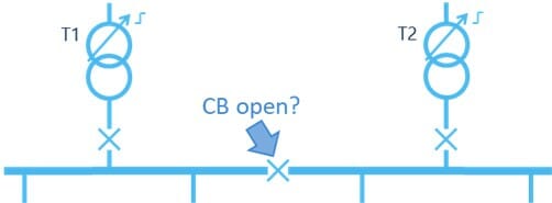
Sometimes it is enough to operate transformers independently with their interconnecting busbar CB open (as in Figure 1), however this will result in a supply interruption for the loss of one transformer, until a changeover can be instigated to resupply the dead segment. However, on many occasions it is preferred to operate the substation with the busbar CB closed, but this is prevented by poor voltage control imposing operating limitations.
Using the Auto Transfer Switching (ATS) method, the relays monitor each transformer and send information to each other. For example, if transformer T1 went out of service, the relay connected to T1 will send a message to the relay connected to transformer T2, which would then send a signal to close the busbar circuit breaker CB and provide supply to the feeders relating to the out of service transformer T1. Therefore, it follows that, since it is always possible to parallel transformers2 as outlined above, it is always possible to operate with n-1 security.
Losses
Many LV distribution systems are designed for a wide operating range, and consequently so are equipment and appliances. For example, in the EU the operating range is 230 V +10% -6%, which equates to a range of 216 V to 253 V, while all equipment must be designed to operate at 230 V ± 10%, or 207 V to 253 V. In order to operate across this range, equipment will have a design or reference voltage at the lower end. In many cases, upper limit voltages on the range will result in increased losses within the equipment, but if the voltage of the LV system can be maintained at the lower end of the permitted range, then losses will be reduced.
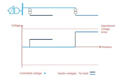
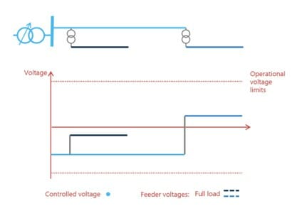
Figure 2(a) shows how AVC and LDC play a significant role in facilitating this. The example shows a primary substation transformer (sky blue line), which is usually the last point for regulation of voltage, and two distribution transformers with fixed taps, one close to the primary transformer (navy blue line) and one some distance from it (light blue line).
The no load situation, as shown by the solid lines, shows the disadvantage, in that the voltage at the far end is close to the upper voltage limit. The results of this are (i) inefficiencies and losses within customer loads which have a design voltage at the lower end of the range, and (ii) no room to accommodate any connected generation, for instance in the form of rooftop solar panels.
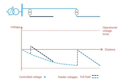
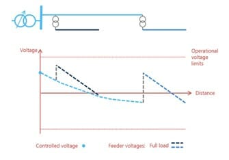
Often the distribution transformer furthest from the primary substation will have a higher tap selected than the closer distribution transformer. The reasons for this can be seen in the graph of Figure 2(b) which shows the per unit voltage through the system (solid sky-blue line). The dashed lines show the full load situation where even with the boost through the distribution transformers, the voltage approaches the lower limit in the LV system of the further transformer. Figure 2(c) and 2(d) provides the answer for this in the form of LDC, or line/load drop compensation. The AVC system is set with a target voltage below nominal, but with an LDC boost to bring it back near to nominal. For example, a basic voltage target of 97%, and a boost to the target at full load of +4% means that when there is no load the system will be close to the lower end of the permitted range, with plenty of headroom for the connection of PV. When the load is full, the voltage is boosted back to just above nominal to ensure that the network stays within its limits.
Figure 2 Voltage regulation
Network Utilisation
Increasing the utilisation of expensive assets such as transformers is an effective way to increase capacity.
Paralleling across networks is an easy method to achieve this, while maintaining n-1 security criteria, as highlighted in Figure 3.
Figure 3 Network utilisation
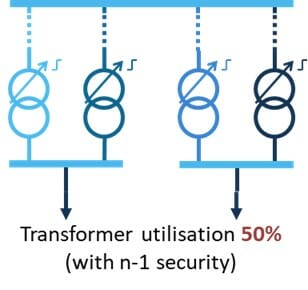
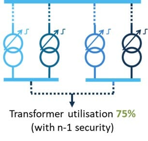
In Figure 3(a) to operate with n-1 security, it is only possible to plan loading of the network to 50% of its capacity (for the loss of 1 of 2 transformers), whereas in Figure 3(b) if the networks are interconnected then the loss of 1 of 4 transformers allows a loading of 75% of capacity.
In order to achieve this, the AVC system needs to be capable of supporting the paralleling of transformers across networks. For this, a negative reactance-based system is required, which minimises circulating current flows between the parallel transformers.
Engineering Efficiency Benefits
The previous sections discussed the efficiency benefits that an optimal AVC system can bring to the network and customers. However, there are also efficiency benefits to network operators in the form of lower expansion costs.
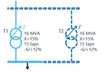
Figure 4 shows the expansion of a substation with an existing transformer T1, and the addition of a second transformer T2. If the master-follower method of AVC is used this will require the approach of Figure 4(a) where an identical transformer is used and it is connected to the same source with no infeed arrangements on the incoming line. If the existing transformer is old, it may be unnecessarily expensive to source an identical transformer from the same supplier. The master-follower method also imposes a constraint in how the new line is brought to the substation – the source impedance needs to be the same on both lines and there can be no tees which may draw load or inject generation.
Figure 4 Substation expansion
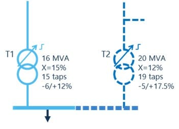
Because the Enhanced TAPP method allows the use of differing transformers and voltage sources, these constraints are removed. The operator can source a transformer from their current framework or supply arrangements, without concern over matching it with the existing transformer, therefore getting cost efficiencies. This is illustrated in Figure 4(b) showing differences in transformer rating, impedance, tap spacing, number of taps, and with different infeed arrangements.
Conclusions
The Electrical Power System has remained largely unchanged for the past century. However, due to the ever increasing strain that we put on the grid as demand for energy increases, it has become absolutely necessary for network operators to reinforce the system and maintain a steady supply of electricity to customers, preventing premature loss of life of network assets.
Using the Enhanced TAPP methodology of voltage control provides additional options to the network operator with the benefits of:
- Always maintaining at least n-1 security of supply,
- Extending substations more cost-effectively using any available transformer (no need to match transformers),
- Increasing network utilisation (while maintaining security of supply) through paralleling substations across the network,
- Reducing losses in customer load by operating closer to the target voltage,
These features help to extend the lifetime of key network reinforcement costs and meet the networks ever-changing obligations.
Notes
1 AVC and AVR (C=control, R=regulation) are both used to refer to the control system for on-load tapchangers in different parts of the world. In this paper AVC is used throughout.
2 Except for fault level restrictions.
Abbreviations
AVC automatic voltage control
AVR automatic voltage regulation, equivalent to automatic voltage control
CB circuit breaker
EU European Union
LDC line, or load, drop compensation
LV low voltage, i.e. less than 1 kV
OLTC on-load tapchanger
PV photovoltaic generation
About the Authors
Vincent Thornley has 20 years’ experience of energy-orientated technology crossing many fields, including nuclear generation, connection of renewable energy, smart grid technologies, and integration of heat, power and transport. He gained a doctorate for his research in voltage control and active network management, a forerunner of the smartgrids of today. Dr Thornley is a chartered engineer (CEng) and a member of the Institution of Engineering and Technology (MIET).
Elizabeth T. Macharia is an electrical and electronics engineer with technical and leadership experience within the smart transformer technology, electricity utility, building services, and grid control industries. Miss Macharia is a member of the Institution of Engineering and Technology (IET) and volunteers as the Young Professionals ambassador for her local network. Her interests include but are not limited to power systems, sustainable energy, innovative technologies that drive change within the engineering industry, and STEM education and outreach.
Learn more

- Article
- Automatic Voltage Control (AVC/AVR)
New challenges. New tools.

- Article
- Automatic Voltage Control (AVC/AVR)
Fundamentals’ delivery strategy

- Article
- Automatic Voltage Control (AVC/AVR)
Demolishing barriers to smart digitised substations
- Article
- Automatic Voltage Control (AVC/AVR)